Professional·One-stop Services
Get customized solution and favorable quotes here: +86 13526692320

The difference between a screw-type continuous pyrolysis reactor and a continuous rotary kiln pyrolysis reactor comes down to one thing: how the plastic is pushed through the hot zone. A screw pyrolysis reactor drags the feed forward with a turning auger. A continuous rotary kiln pyrolysis reactor lifts and drops it inside a slowly turning drum. That single design choice decides how each machine handles molten plastic, mixed film, wear and floor space. Neither is better in general. Screw pyrolysis reactors suit clean, uniform feed at modest capacity; rotary kiln pyrolysis reactors suit mixed plastic at larger scale, and ask for more space and more seal maintenance.
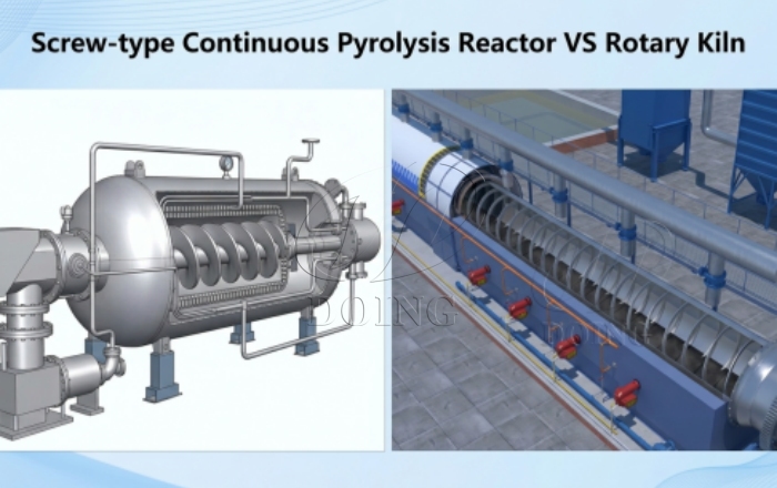
Screw-type continuous pyrolysis reactor VS rotary kiln pyrolysis reactor
A screw-type continuous pyrolysis reactor is a heated tube with an auger running through the centre. Plastic is metered in at one end, the turning flights push it forward as it melts, and char leaves at the far end. Heat arrives through the tube wall, a hollow shaft, or both, so the same component that conveys the bed also stirs it against the hot surface.
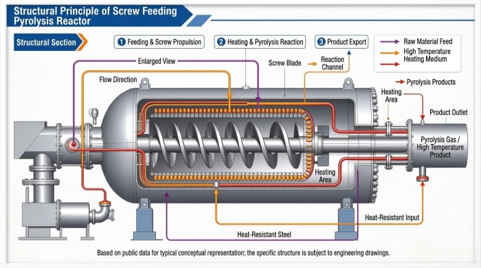
screw-tpye pyrolysis reactor brief introduction
A continuous rotary kiln pyrolysis reactor works the other way round: the drum is the conveyor. It sits at a slight angle on support rollers and turns slowly, while internal lifters carry material up the wall and let it fall back through the hot gas. Every turn advances the bed a little toward the discharge end. Nothing inside the drum pushes the plastic along.
That is the whole difference in one sentence. In a screw pyrolysis reactor, transport and heat come from one moving part sitting inside the hot zone. In a rotary kiln pyrolysis reactor, the vessel moves and the internals stay passive.
| At a glance | Screw-type continuous pyrolysis reactor | Continuous rotary kiln pyrolysis reactor |
|---|---|---|
| What moves the feed | Auger flights pushing against the bed | Drum rotation, lifters, gravity |
| Where heat enters | Tube wall, hollow shaft or both | Shell wall, hot gas, burner zones |
| Residence time set by | Screw speed | Drum speed, slope and internal dams |
| Moving parts in the hot zone | Auger and shaft, full length | None; the shell itself turns |
| Space per tonne of capacity | Compact, can stack parallel tubes | Long footprint, heavy foundation |
Plastic does not stay granular for long. Within the first metres of the hot zone it softens and turns into a sticky melt that behaves more like warm tar than like sand. How a reactor handles that melt decides how often the line stops, and this is where the two designs separate most clearly.
A screw pyrolysis reactor has two weak points. The melt coats the flights and the shaft, and the layer grows until the gap between flight edge and tube wall closes. Film, woven bags and any fibre in the feed make it worse, because they wrap around the shaft instead of breaking apart. Once the gap closes, torque climbs, the drive trips, and clearing means opening a hot reactor.
A rotary kiln pyrolysis reactor avoids narrow clearances altogether. No flight edge runs close to a wall, so a wrapped film has nothing to jam against. Lifters, and in many designs loose chains, knock material off the shell as the drum turns. Sticking is not impossible, since a hot spot can still build a ring of carbonised plastic, but it becomes a temperature-control problem rather than a mechanical clearance problem.
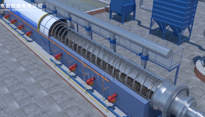
Continuous rotary kiln pyrolysis reactor internal design
In a continuous screw pyrolysis reactor, heat reaches the bed through the tube wall and often the hollow shaft. That gives a high heated surface area inside a small machine, which is why screw pyrolysis reactors come up to temperature quickly and hold a setpoint closely. The same closeness carries a risk: a film of melt resting against an over-hot wall carbonises and then insulates the wall behind it.
A continuous rotary kiln pyrolysis reactor heats a bed that is constantly lifted and dropped, so fresh surfaces meet the hot gas and the shell. Temperature spreads more evenly across the bed, which matters when the feed mixes plastics with different melting points. The trade-off is inertia. A large drum takes longer to fill and to bring to temperature, and burner zones along its length do the work of keeping the middle from running hot.
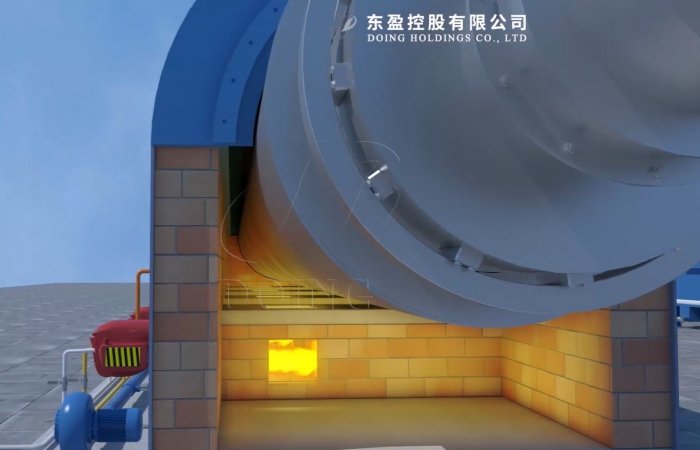
Rotary kiln pyrolysis reactor indirect heating method
Pyrolysis needs an oxygen-free hot zone, so every opening is a potential fault. On a screw pyrolysis reactor the inlet and outlet are small, and the feed often forms its own plug; shaft seals at each end are compact and easy to reach. On a rotary kiln pyrolysis reactor both ends are large rotating joints, and both wear. Seal condition decides whether air leaks in and whether gas escapes around the shell.
Gas leaving the reactor also carries fine char. A kiln discharges gas from a wide chamber and can carry more dust into the first condenser, so the cyclone and condenser have to be sized for that load. A screw reactor has a narrower gas outlet that is easier to keep clear, but a blockage there stops the line faster.
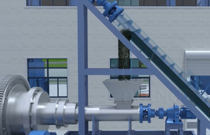
Continuous rotary kiln pyrolysis reactor sealed screw feeding method
The mechanical difference becomes a layout difference. A screw pyrolysis reactor is compact and can be built as several parallel tubes on one frame, which suits sites where space or headroom is tight. A continuous rotary kiln pyrolysis reactor needs length: a 50 t/d continuous configuration typically occupies around 1,200 m² once the drum, foundations and access routes are counted.
Scale follows the same logic. Auger capacity is limited by tube diameter and by how much heat can pass through the wall, so single-train screw reactors stay in the small to medium range. A kiln scales by growing longer and wider, which is why most plastic lines at 50 t/d and above are built around a continuous rotary kiln pyrolysis reactor.
Maintenance tracks the wear points. Screw pyrolysis reactors wear at flight edges, the hot-end bearing and the shaft seal, and a worn flight loses conveying capacity quietly before it fails. Kilns wear at tyres, rollers, the girth gear and the two end seals, and those are planned replacements rather than surprises.
| Your situation | Lean toward | Reason |
|---|---|---|
| Clean, single-grade plastic, shredded or pelletised, up to roughly 20 t/d | Screw reactor | Close temperature control, compact sealed tube, even residence time |
| Mixed post-consumer plastic with film, labels, fibre and grit | rotary kiln pyrolysis reactor | No narrow clearance to jam, tumbling bed tolerates shape and size variation |
| 50 t/d or more on a single train | Continuous rotary kiln pyrolysis reactor | Throughput grows with drum size rather than with the number of tubes |
| Tight site, limited headroom, phased investment | Screw reactor, parallel trains | Short vertical layout, modules can be added in stages |
| Small maintenance team | Compare wear-part access first | Both designs need scheduled seal and wear checks |
Answer these before you compare quotations. What does your feedstock look like after sorting: pellets, flakes, film, or bales of mixed bags? What daily tonnage must run, and must it run around the clock? How much flat ground and headroom do you actually have? Who clears a jam at two in the morning, and how long can the line afford to stay down?
Most buyers discover the answer is a limit rather than a preference. Film-heavy mixed feed at high tonnage points to a kiln. Clean, single-grade feed at modest tonnage points to a screw reactor. Ask for a quotation against your own feedstock analysis, not against a generic capacity table.
DOING ECO builds fully continuous plastic pyrolysis machines around a rotary kiln main reactor, with sealed screw feeding and discharge, three-stage sealing and PLC control; the DY-C series covers 15, 20, 30 and 50 t/d per line. For clean, uniform feed at low tonnage, a batch or semi-continuous machine is usually the better fit, and we say so before quoting. Henan DOING Environmental Protection Technology Co., Ltd supplies both the continuous and batch configurations.
Feedstock decides most of it. Oil yield follows plastic type and cleanliness far more than reactor design. Reactor design affects consistency instead: even temperature and controlled residence time reduce heavy wax and char fines in the oil, and good sealing keeps combustible gas inside the system where it can be reused.
Only with preparation. Film wraps around the auger and bridges the inlet, so it needs shredding and often densifying before feeding. Even then, throughput drops and clearing stops become routine. A rotary kiln pyrolysis reactor tolerates film better because nothing inside the drum winds material up.
Mechanically yes, with limits. Tires bring steel wire and behave differently in the hot zone, while plastic melts into a sticky mass. A kiln copes with both through adjusted temperature and discharge settings; a screw reactor is more sensitive to that change in consistency. Run a test on each feedstock before committing.
The screw pyrolysis reactor is harder. Cooled plastic sets around the flights and has to be cut out through inspection openings. A kiln cools into a bed that can usually be broken up and run out through the discharge. Neither job is pleasant, but the kiln is more accessible.
In a screw pyrolysis reactor, by screw speed. Slower turns mean longer time in the hot zone, and the relationship is direct. In a rotary kiln pyrolysis reactor, drum speed, slope and internal dams work together, so changing one means rebalancing the others.
No, but it is the usual one. At that tonnage, single-train screw reactors become difficult to scale and costly to maintain. If your feed is clean and uniform, several parallel screw trains can still offer better economics than one large drum.
Send your feedstock mix, daily tonnage, available ground area and target product. We will reply with the reactor type that fits, a process flow diagram and an equipment list for that duty. Layouts and running figures for the continuous rotary configuration are published on our continuous plastic pyrolysis plant page.
Figures are indicative and depend on feedstock and site conditions. Final performance is confirmed by a material test and the agreed technical proposal.
Leave A Message
Leave A Message