Professional·One-stop Services
Get customized solution and favorable quotes here: +86 13526692320

Every pyrolysis plant — whether it runs on waste tires, waste plastics, aluminum-plastic composites or oil sludge — follows the same six-step workflow: feed, heat, condense, recycle the gas, discharge, store. What changes with the feedstock is not the sequence but four variables: the pyrolysis temperature, the pre-treatment the material needs, the protection the oil-vapour path needs against wax and coke, and the way solid residue leaves the reactor. Each variable decides the configuration, the running cost and, in the worst case, whether the pipes clog in the first week. A pyrolysis plant manufacturer such as DOING ECO matches the configuration to whichever variable your feedstock pushes hardest.
The common workflow runs like this. Material enters the reactor through a screw feeder or, for liquid feeds, a pump. The furnace raises the reactor temperature until the organic fraction cracks into oil vapour — as a reference point, vapour leaves the outlet at around 350°C while the furnace itself runs near 500°C. The vapour passes into a buffer tank fitted with a pressure gauge and a relief valve, then through multi-stage condensers — vertical and horizontal shell-and-tube types, or water-tank condensers — where it liquefies into pyrolysis oil and drains into a storage tank.
Gas that will not condense — methane and other light hydrocarbons — is sealed, washed and returned to the furnace as fuel, so after start-up the plant largely heats itself. When the run ends, the reactor cools and the solid residue leaves through the discharge ports: carbon black, plus steel wire when tires are processed. Throughout, the reactor works at atmospheric pressure — production pressure stays below 2 kPa, usually under slight negative pressure — and fully enclosed, whatever the material inside.
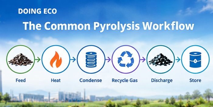
Key stages of pyrolysis
Waste tires crack at 320–350°C and yield roughly 45% oil from truck tires and about 35%-40% from car and bicycle tires, with steel wire and carbon black as the other outputs. The more wire a tire carries, the slightly lower the oil yield. The wire is pulled out and sent straight to steel mills; the carbon black is packed and sold.
Pre-treatment is the branch point. A batch pyrolysis plant takes whole tires directly — no washing, shredding or wire pulling before the feed. Semi-continuous and fully continuous pyrolysis plants need the opposite: tires reduced to 16–18 mesh rubber powder first, with the wire separated before it reaches the reactor.
Because tire pyrolysis tends to coke on the reactor wall, these plants carry scraper devices that keep the inner surface clean. All three discharge arrangements — front, side and rear — work with tires, chosen mainly by site layout, so the same feedstock leaves room to fit the plant around the yard rather than the other way round.
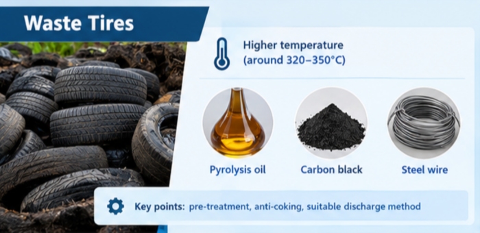
Waste tire feedstocks and outputs
Plastics crack at the lowest temperatures of the common feeds, 300–320°C, but the type of plastic decides the yield far more than the temperature does. The three commodity plastics dominate real-world volumes. Clean polyethylene (PE) — film, bags, bottles, oil drums — reaches about 95% oil. Polypropylene (PP) — woven bags, ropes, basins, plastic furniture — and polystyrene (PS) — food containers, appliance housings, foam packaging — both sit near 90%.
Beyond the big three, the spread widens quickly. Pure plastic cable sheathing gives about 80%; clean white plastic sheeting about 70%; clean plastic bags above 50%. ABS and PMMA engineering plastics drop to around 40%. Mixed or dirty plastic falls to 20–30%, and printed label stock to around 20% — which is why sorting pays directly in output.
| Plastic type | Typical sources | Oil yield (clean feed) |
|---|---|---|
| Polyethylene (PE) | Film, bags, bottles, oil drums | ~95% |
| Polypropylene (PP) | Woven bags, ropes, basins, furniture | ~90% |
| Polystyrene (PS) | Food containers, appliance housings, foam | ~90% |
| Pure plastic cable sheathing | Wire and cable coating | ~80% |
| Clean white plastic sheeting | Agricultural and packaging film | ~70% |
| ABS / PMMA engineering plastic | Appliance panels, acrylic sheets | ~40% |
| Mixed or dirty plastic | Unsorted household plastic | 20–30% |
| PET | Beverage bottles | Not suitable for oil |
| PVC | Pipes, shoe soles | Chlorine content — avoid |
Two types stay out of the reactor altogether. PET cannot be pyrolyzed into oil, and PVC should not be, because of its chlorine content.
The defining difference of plastic feed is wax. Plastic oil begins to solidify below roughly 18–20°C, and wax building up in pipes and condensers raises pressure and creates a safety risk. So a waste plastic pyrolysis plant adds a dewaxing tank between the buffer and damping stages, fits heating belts along the vapour pipes, enlarges the condenser tubing, and uses water-tank condensers that tolerate wax better. A heating coil wound around the crude oil tank keeps the finished oil pourable in cool weather.
Discharge goes front or side rather than rear, and a semi-continuous pyrolysis plant is generally not recommended for plastics — light, fluffy material will not pack under the feeding screw.
Aluminum-plastic waste — composite panels, pharmaceutical blister packs, laminated films — runs the hottest of the common feeds at 350–380°C, with double burners firing for roughly 29 hours per cycle, and yields 50–55% oil. Being a petrochemical-derived laminate, it shares the wax concern of plastics, so the vapour path carries the same heating-belt protection.
Its quirk is the other product. Aluminum does not come out as powder but as large lumps, and lumps that size cannot pass a rear discharge screw. The plant is therefore configured with side or front discharge, and the residue leaves at around 150°C — a case where the shape of one product dictates the layout of the whole discharge side.
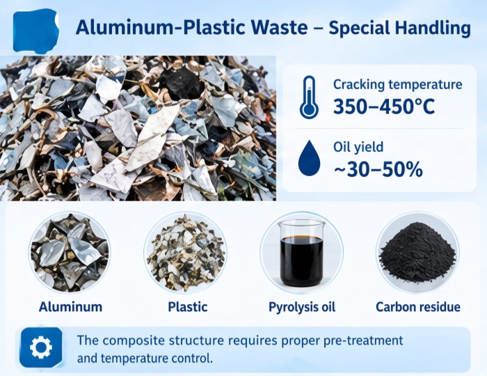
Aluminum plastic pyrolysis processing requirements
Oil sludge behaves differently again. It is a hazardous-waste feed that cracks above 400°C, and because it is liquid or semi-liquid it is pumped into the reactor rather than screwed. Tank-bottom sludge can carry 70–80% oil; steel-mill and rolling-mill sludges carry 10–30% oil together with up to 50–70% iron, and expand strongly on heating, so the reactor is protected against foaming and pressure spikes.
Its high viscosity cakes onto the reactor wall, where a coke layer blocks heat transfer and shrinks the working volume. The plant therefore carries energy balls — heat-storing steel balls that tumble through the material at roughly one-to-one volume, dispersing it, conducting heat, scraping coke and refining the residue — or a toothed descaling bar that rotates with the reactor and scrapes the wall clean.
Semi-continuous pyrolysis plants handle sludge through separate solid and liquid feed ports, so one batch can take sludge pumped in and the next take shredded solids. Oil-based drill cuttings show how far the variation goes: after centrifugal dewatering they give up oil at just 160–170°C, cool and quick enough for a fully continuous plant.
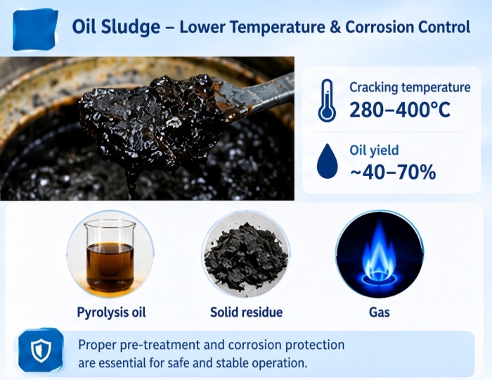
Aluminum plastic pyrolysis processing requirements
| Feedstock | Pyrolysis temperature | Oil yield | Key workflow difference |
|---|---|---|---|
| Waste tires | 320–350°C | ~45% truck tires, ~40% car tires | Batch takes whole tires; continuous needs 16–18 mesh powder; scraper anti-coking; three discharge options |
| Waste plastics (PE/PP/PS) | 300–320°C | ~95% clean PE, ~90% PP/PS | Dewaxing tank + pipe heating belts + water-tank condensers; front or side discharge |
| Aluminum-plastic waste | 350–380°C | ~50–55% | Double burners, ~29 h cycle; aluminum lumps force side or front discharge |
| Oil sludge | above 400°C | 70–80% oil content in tank-bottom sludge | Pump feeding; energy balls or descaling bar anti-coking; solid and liquid feed ports |
| Oil shale | 480–500°C | 5–20% oil content | Highest temperature band; longest heating schedule |
The same feedstock runs to a different rhythm on each machine class.
A batch pyrolysis plant completes one cycle — load, heat, condense, cool, discharge — in about 20 hours, and tolerates irregular supply. Inside that cycle, a forced cold-air system cuts reactor cooling to roughly 4–5 hours against 10–12 hours of natural cooling, and two-way 180° discharge ports shorten carbon black discharge from about 4 hours to 2.5 hours. It is the class with the loosest pre-treatment demand and the lowest entry cost.
A semi-continuous pyrolysis plant feeds through an enclosed screw and a ball valve, produces oil in roughly 10 hours and runs two days out of every three batches. A water-cooled discharge screw lets carbon black leave hot and enclosed instead of waiting for a full cool-down. With its dual solid and liquid feed ports, it is the class that switches between pumped sludge and shredded solids.
A fully continuous pyrolysis plant, fed with powder no larger than 5 mm through a metering belt, runs 45 to 60 days without stopping. An internal propeller moves material forward as the reactor rotates, while slight negative pressure draws the oil vapour backwards, separating vapour from carbon black cleanly. Three-stage water-jacketed discharge screws cool the carbon black as it leaves, and the non-condensable gas — about 12% of output — can be pressurized and used for power generation.
| Machine type | Feed form | Rhythm | Suits |
|---|---|---|---|
| Batch pyrolysis plant | Whole tires or whole material | ~20 hours per cycle | Mixed feedstock, no shredding line, first plant |
| Semi-continuous pyrolysis plant | 16–18 mesh powder or shredded feed; sludge pumped | ~10 hours to oil, batches in rotation | Stable powder supply; switching solid and liquid feeds |
| Fully continuous pyrolysis plant | Powder below 5 mm | 45–60 days continuous | Large projects with their own shredding line |
Choose by feed form and volume first: whole tires with no shredding line point to batch; steady powder supply points to semi-continuous or fully continuous. The machine class then fixes the rhythm, and the feedstock fixes the temperature, pre-treatment, vapour-path protection and discharge.
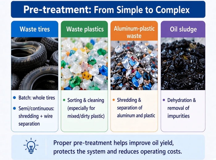
Preparing feedstock for pyrolysis
DOING ECO builds all three machine classes and skid-mounted pyrolysis plants, delivered to more than 120 countries, and configures each one around the four variables above: heating matched to the cracking temperature, dewaxing or anti-coking devices matched to the material's behaviour, and discharge matched to its residue. Feedstock testing before the order sets the temperature schedule and the expected yield. DOING ECO sends engineers for on-site installation and operator training, so the workflow described here is what the plant actually runs.
DOING ECI pyrolysis plant manufacturing expertise
Send your feedstock type, its form — whole, shredded or pumped — and your daily tonnage, and the configuration can be matched to the four variables that actually decide the workflow: temperature, pre-treatment, vapour-path protection and discharge.
Leave A Message
Leave A Message